Mexico

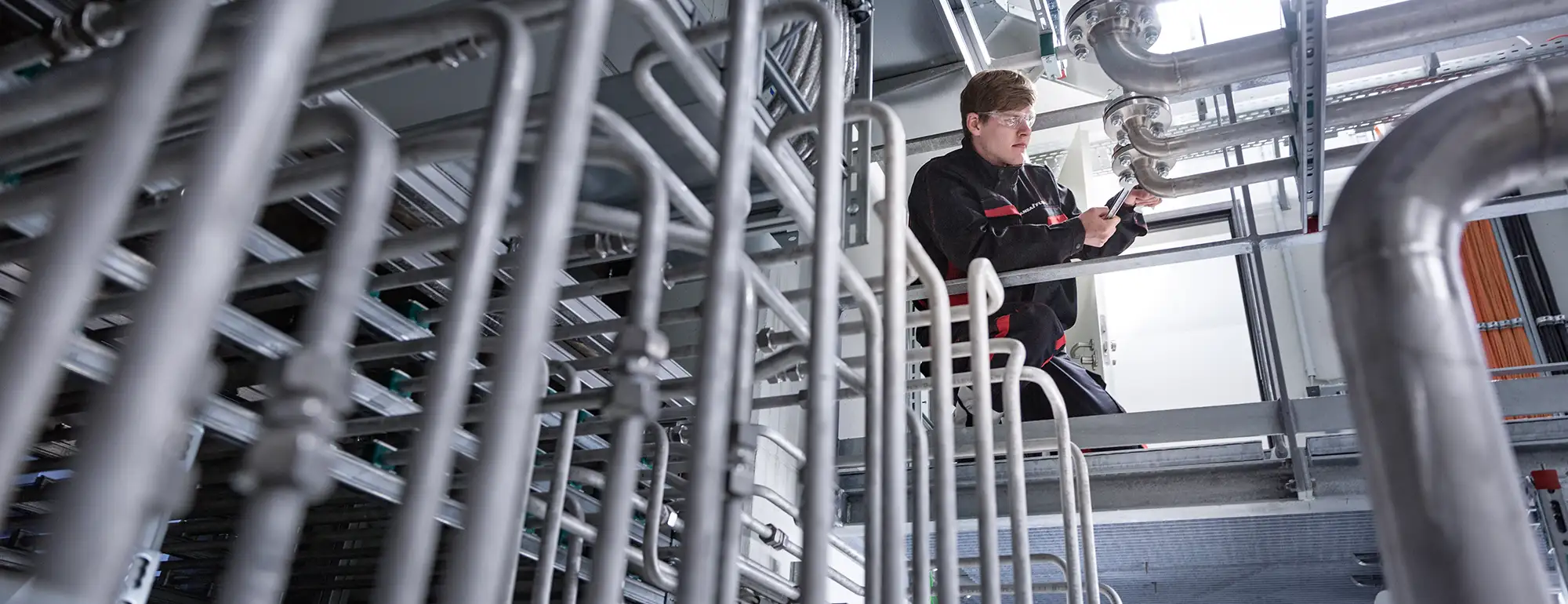
Maintenance work on machinery in general and on hydraulics in particular involves risks and hazards. For this reason, a risk analysis has to be carried out for this type of work in accordance with the Ordinance on Industrial Health and Safety, and documented together with the resulting protective measures. Maintenance personnel also have to be instructed in the dangers that can occur and the protective measures that have to be taken as a result.
A particular hazard is the sudden escape of fluid under pressure. When clamping elements that are still under pressure are released, it must therefore be expected that pressurised fluid will escape. The consequences can be many and varied. A particularly common injury is when hydraulic fluid penetrates the skin. This can lead to serious injuries, and in the worst case to death. But scalding by hot pressurised fluid, fire hazards, the risk of slipping as well as danger from machinery unexpectedly starting up are also possible consequences. For this reason any machinery and machine parts for which maintenance work is to be carried out on the hydraulics must first be rendered free from pressure.
Caution: residual pressure when machines are switched off!
Many maintenance technicians carelessly assume that the hydraulic system is completely free from pressure when the machine is switched off. However, it should be noted that there are situations in which residual pressure may still be present even after the machine has been switched off.
Maintenance work on the hydraulics of machines involves risks and dangers - for example, due to the uncontrolled escape of the pressure fluid.
Shut-off valves are often installed in hydraulic systems to hydraulically clamp the consuming unit, and prevent unintentional activation by the load acting on the consuming unit. The valves allow free flow in the direction of the consuming unit and block any flow in the opposite direction. Such shut-off valves are, for example, releasable non-return valves or electrically switching directional control valves, and are referred to in practice as “load-holding valves” in accordance with their function. To ensure that they can also effectively prevent the unwanted movement of the consuming unit, these valves are designed as seat valves and are virtually leak-proof. Due to this relatively high degree of tightness, pressure can still be present even after the machine has been switched off. It is therefore imperative before loosening a screw connection to check that there is no pressure behind it. Unfortunately, this check is difficult in practice because the necessary measuring points are often not available. If this is the case, the maintenance technician needs to use the hydraulic circuit diagram to check what possibilities there are for depressurising the line in which the system is to be disconnected. For example, if the technician wants to access Line A1 (see circuit diagram Fig. 1), the hydraulic cylinder can be retracted as far as it will go. Line A1 is connected to the tank via the directional control valve (WV) and is therefore free from pressure.
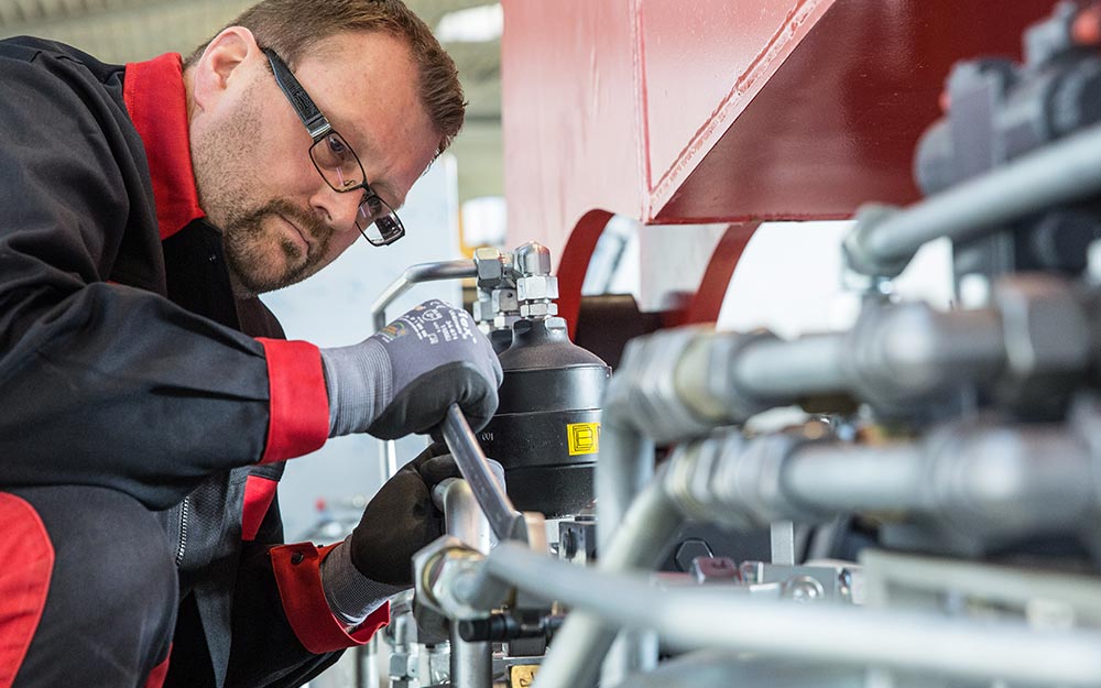
Another load-holding valve in seat valve design is the lowering-brake valve. It is installed in hydraulic systems on consuming units with which lifting work is performed and ensures controlled lowering of the load. Here too, when the hydraulics are switched off, pressure can be trapped downstream of the valve in the direction of the consuming unit. In machines such as excavators, pipe rupture safety valves with a load-holding function are found on the boom cylinders (Fig. 2) and stick cylinders. In practice, these valves are often mounted directly on the hydraulic cylinder and should only be dismantled when the absence of pressure in the cylinder chamber has been ensured.
Before disassembling load-holding valves or loosening connecting elements downstream from these valves, loads that are held up must normally be lowered or propped up, and any residual energy must be dissipated.
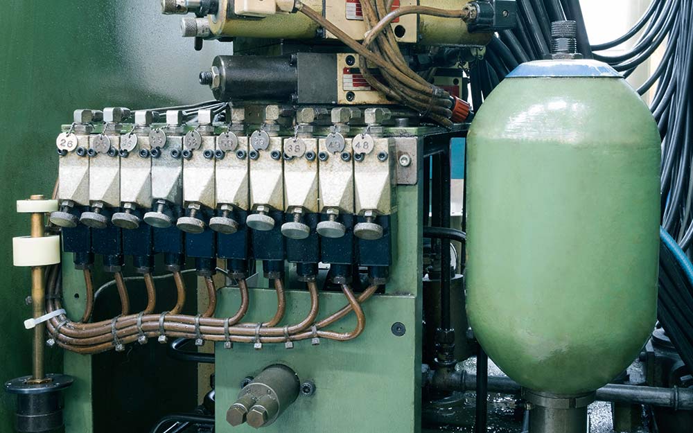
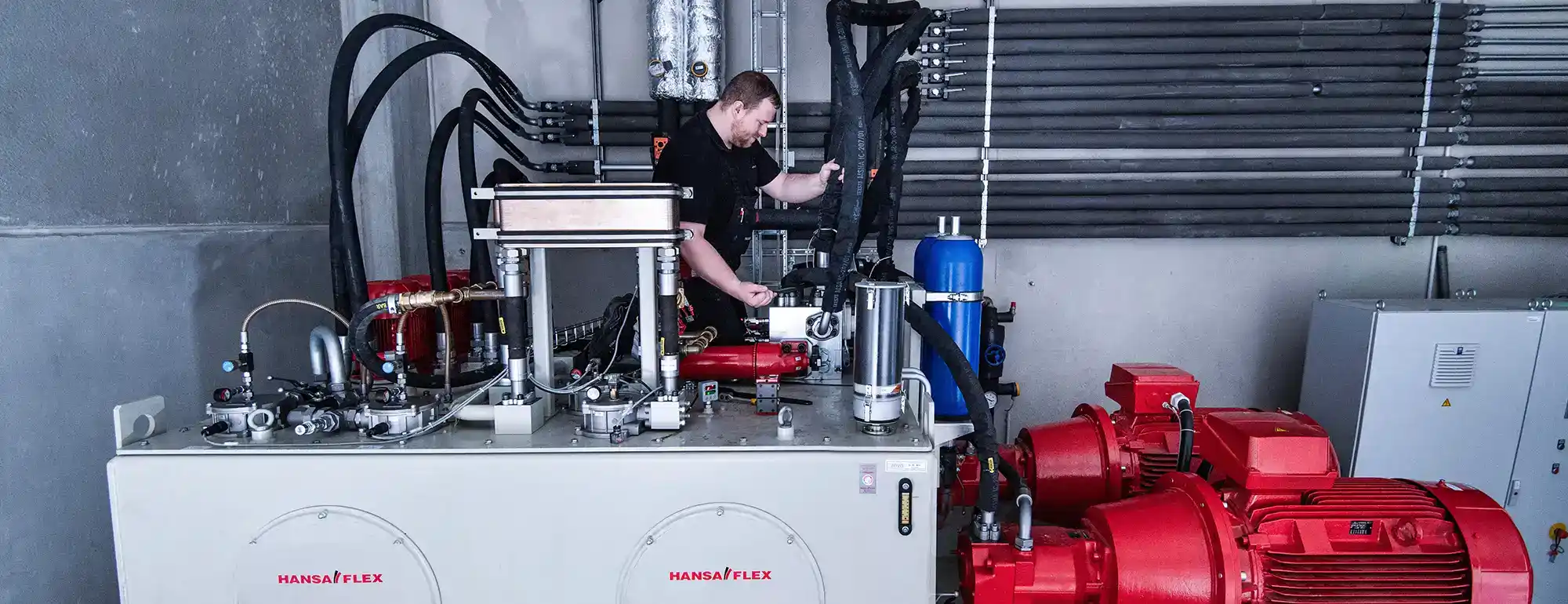
Gas pressure storage facilities pose an increased risk potential due to residual energy, as a compressible gas is used to store the oil volume.
After a machine has been switched off, gas pressure accumulators pose a further danger due to their residual energy. Their task is to store a certain amount of oil under pressure and to release it when needed. Since compressible gas is used to control the oil quantity, gas pressure accumulators pose an increased hazard potential. If a connection is loosened in a line containing a gas pressure accumulator, the decompression of the gas can result in a sudden escape of oil, which can cause serious injuries. Although DIN EN ISO 4413 stipulates that an accumulator must be automatically depressurised after the machine is switched off, this is not always possible. An example of this is machinery on wheels. With such machinery control pressure is required to activate the directional control valves. If the machine does not have its own control oil pump, this is taken from the main system. Gas pressure accumulators are installed so that these valves can still be operated (for lowering loads, for example) even if the hydraulics fail. In order to achieve the described function, they are not depressurised after the machine is switched off.
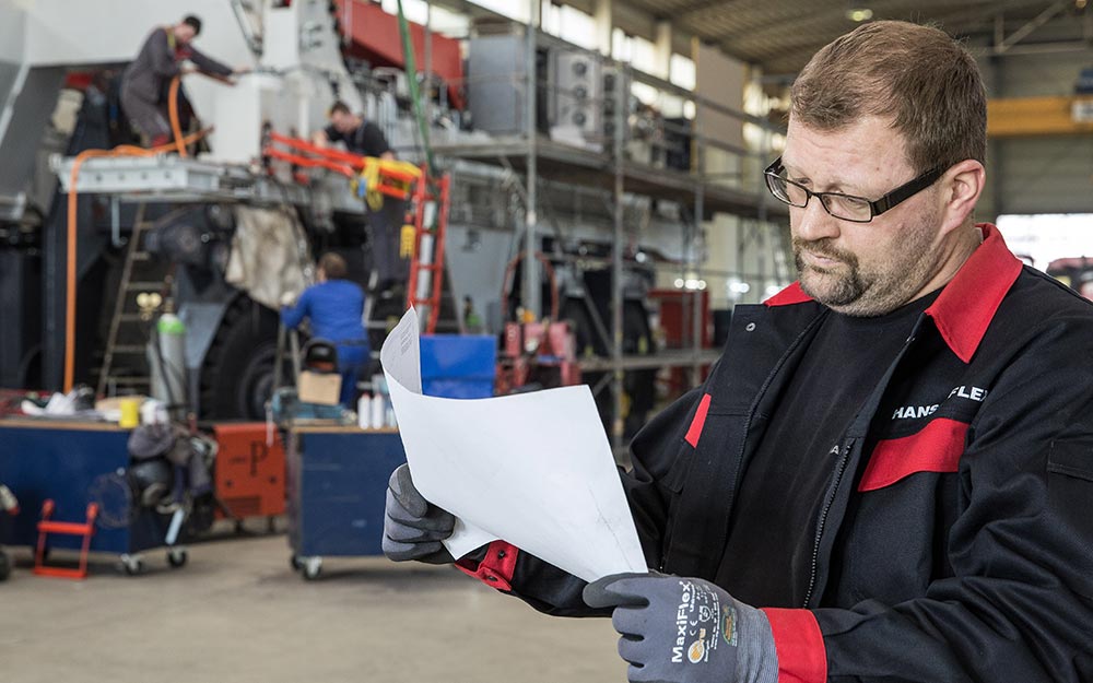
The ability to read machine circuit diagrams is essential in order to check freedom from pressure.
The problem for the maintenance technician is that the valves and accumulators described are often not located directly at the location the technician wants to work on. If the corresponding measuring point for checking the absence of pressure is also not available, the ability to read machine circuit diagrams is indispensable. This requires knowing the structure and function of the hydraulic components hidden behind the symbols and understanding how they interact. This is referred to as the necessary "technical expertise", which all maintenance staff need to have when carrying out maintenance work in accordance with the German Ordinance on Industrial Health and Safety. The IHA Schulungs gGmbh seminars help technicians to acquire this expertise.
-

Dipl.-Ing. (FH) Frank Weigel
Trainer Fluid Technology of the International Hydraulics Academy